These are intended as a guide only, always seek the advise
of a qualified engineer and use experienced fitters.
Standard galvanized support bracket strip curtain fitting instructions.
(1) The Support bracket may be fixed to the face or the underside of the door lintel,
to the wall above the doorway, or optionally with brackets to a 75mm or 100mm RSJ. (see fig 8,9 & 10).
If the optional jointing angle brackets are to be used, assemble the support bracket on the floor.
(A) Position the connector inside the support bracket across the ends of the sections to be joined.
(B) Place one hanger plate in the position across the joint to ensure correct spacing of the support bracket hook,
Note: hanger plate should be removed before fixing support assembly in place.
(C) Fix the support bracket sections together with bolts:
a) through vertical face for installation under a door lintel or on an RSJ
b) through the horizontal (upper) face for a flat mounting against a wall or lintel.
(2) Length adjustment.
When the support bracket is to be mounted under a lintel or on an RSJ between the door jambs,
it is necessary to allow at least a 12mm gap between each end of the bracket and the door jamb.
If the completed support bracket assembly is too long, simple saw the required
amount off one end, making the cut between two hooks.
(3) Strip assembly.
a) To determine the required length of strips, measure the height of the opening (dimension a),
(for lintel & RSJ mounting) subtract 120mm, so that when the strips are hung on the support bracket
the gap between the bottom of the strip and the floor is 3mm-6mm.
b) Cut the strips to length with the knife and right-angle cutting guides.
c) Punch two(200mm width PVC), three (300mm width PVC) or four holes (400mm width PVC) into the head
of each strip using the optional template as a guide, ensure that its edge is level with the end of the strips.
d) Bolt the hanger plate and backing plate and backing plate to the head of each strip so that :
a) the outer curve of the strip (outer surface of the roll is on the convex side of the hanger plate;
b) the bolt heads are on the backing plate side of the assembly.
4) Support brackets.
Lintel mounting .
Allow at least 12mm between each end of the bracket and the door jamb.
Drill M8 (5/16) clearance holes in the support bracket at 70mm intervals for 200mm,300mm width strips and 50mm intervals for 400mm width strips.
To bolt to concrete beams use fisher expansion bolts or any similar 52mm long m8 expansion bolt always refer to the bolt manufacturers expert instructions.
RSJ mounting
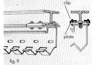
Optional clips an plates can be supplied on request.
Position a plate and one clip every 80cm along the support bracket, with first plate 10cm approx from the bracket end.
Add second clip to fix the brackets to the RSJ.
Face mounting.
Drill M8 (5/16) clearance holes in the support bracket at 70mm intervals for 200mm, 300mm width strips and 50mm intervals for 400 mm width strips.
To bolt to concrete beams use fisher expansion bolts or similar 52mm long M8 expansion bolt always refer to bolt manufacturers expert instructions.
5) Strip arrangement.
Doors used in external opening exposed to wind will need maximum overlap to help prevent draught penetration.
On the other hand, doors where there is heavy traffic flow, or where high loads must pass,
might require a smaller overlap for easier passage. The overlap may be varied in 50mm steps to suit conditions.
Backing strips/overlap strips.
From the installer's viewpoint (see fig.13) the strips numbered 0-1-3-5 etc are called backing strips,
and those numbered 2-4-6 etc. are overlap strips. As an example, take an overlap of 100mm.
Mounting Coefficient (K).
The mounting coefficient (K) is the number of hooks left free between two backing strips.
It varies according to the required overlap and should be increased for internal applications
and reduced for where strong draughts are likely to be present.
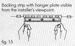
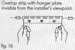
Backing strips should be hung with the bolt heads toward the installer,
while overlap strips should be hung with bolt heads away.
Curtain overlap supplied Strip width mm Mounting Coefficient (K)
L200 R50 200 2 L200 R100 200 0 F300 R50 300 4 F300 R100 300 2 F300 R150 300 0 S400 R150 400 4 S400 R200 400 0
6) Hanging procedure.
Strips.
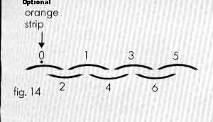
Hang the strips from the support bracket as shown in fig.14. Having chosen a mounting coefficient to suit the exposure of the doorway,
this will determine the number of hooks to be left free between the backing strips (0-1-3-5 etc.).
Hang the strips on the Roman tile principle, i.e. with the concave sides of the strips facing one another.
Start by hanging an optional orange strip at one end (strip 0) of the bracket. Then alternate backing and overlapping strips as shown above.
Complete the door by hanging the remaining optional orange strip on the last hooks.
Note that the last overlap may be non-standard because of the actual size of the opening.
Snap on covers
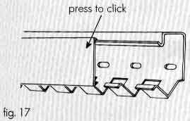
To finish the installation add the support bracket snap on covers.
These are simply positioned on the ends of the hooks then clipped into place over the top lip of the bracket (see fig 17 ).
The Snap on covers are very important as they help to prevent the strips falling off.
© Copyright Ariel Door Gears LTD. All Rights Reserved.